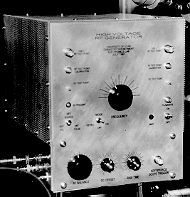
High Voltage RF Generator

Ronald M. Jones
UNIVERSITY OF UTAH
Chemistry Department Electronics Lab
This site contains the user manual, photographs, schematics, technical descriptions, etc. for RF generators developed by the University of Utah Chemistry Department's electronic lab. The device is optimized for powering RF ion guides and traps, and some of its advantages over other schemes, along with some history, are given in an article in Review of Scientific Instruments ("A Simple Radio-Frequency Power Source for Ion Guides and Traps", Ronald M. Jones, Dieter Gerlich, and Scott L. Anderson, Rev. Sci. Instrum. 68 (1997) 3357-62). The purpose of this document is to provide additional practical information on construction, and to allow us to update the circuit diagram as the design continues to evolve.
DISCLAIMER: The information given here is specific to the generators constructed at the University of Utah and as such, much of the information will be of only limited use, however the general circuit descriptions, photographs, etc. may be of benefit in helping anyone wishing to construct their own generator. This circuit employs high voltage RF and DC potentials that can be lethal. Construction and operation of these devices should only be undertaken by those with a good understanding of the hazards. The University of Utah and the authors accept no responsibility for injury or damage caused by flaws in our design or by your failure to exercise care in construction or operation. If you are not comfortable with this, then stick to commercial hardware. The University of Utah nor the authors are obligated to provide any further technical assistance.
The generator at a glance:
The generator is a high voltage oscillator. It is used in the lab to generate a balanced, high voltage RF field. That is to say, there are two output leads which are 180 degrees out of phase with each other. The generator is used to deliver RF to multi-pole ion traps and guides, as discussed in the RSI article. The generator should work in any similar situation where the load is a stable capacitor and stray losses consume only a small amount of power.
The design uses two 6146B transmitting vacuum tubes cross connected in a push pull
oscillator configuration. The tuned circuit for the oscillator consists of an adjustable
tapped coil and a high voltage variable capacitor. The output load (ion guide/trap)
connects directly across the tuned circuit and actually becomes part of the tuned
circuit. As such, it requires no impedance matching circuit and the voltage delivered
to the load is exactly the same as the voltage across the tuned circuit.
The generators also contain a keying circuit which allows the generators to be keyed
on and off with a TTL logic signal, and the rise time of the rf can be adjusted. In
many applications, this keying circuit is not required and the generator is simply
operated in CW mode. In this case, the keying circuit can be omitted.
A DC float voltage may be applied to the outputs and a differential voltage of either
polarity may be applied between the two outputs. The frequency is adjustable from
a few hundreds of kHz to about 25 MHz. The RF generator is contained in a chassis
that is about 8 in. (20.3 cm) wide, 9 in. (22.9 cm) high and 12 in. (30.5 cm) deep..
The generator is powered by an external DC HV power supply that should be adjustable
between 0 and 600V, with at least 50 mA output.
Specifications:
frequency range: approximately 100 kHz - 25 MHz
output peak to peak output voltage. 75 Vpp - 1200 Vpp
float voltage - 0V - +/- 100 Vdc
Links to:
RF generator home page
RF section schematics and description
